Zeta Reticuli: Arduino MIDI controlled 10-band EQ and multiple external effect interface
I. Background
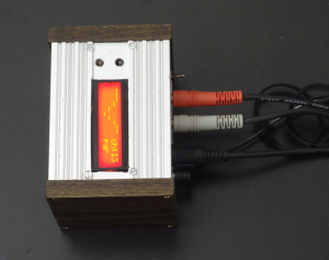
Approximately half my lifetime (20 years) ago I used to have literally drillions & drillions of ideas that I still feel aren’t a complete waste of time. One of these brilliant ideas was to be able to control a guitar wah pedal from my computer. At the time I had scant musical equipment to match my scant muscial abilities. I had scavenged what I could afford in my extremely limited means from pawnshops, flea markets, thrift stores, & the Penny Power. Among this discarded mess were an Atari 1040st computer which has built in MIDI, a Korg Poly800MkI synth, & a Boss DR550 drum machine. I had been successfully using the Atari to sequence the synth & drum machine, but wanted to also control effects for my guitar at the same time and in the same way. But this was the early 1990’s. I didn’t have the skill nor the funds to do anything of the sort.
For those interested here are some YouTube links to a blurry picture of my son playing with the Korg over very randomly spliced together and poorly preserved material salvaged from a cassette made at the time: SLSC-B01 & SLSC-B02
I recently realized that some of these old ideas, due to a better financial situation and the current space age state of technology, are now easily within reach. The first of these ancient plans to be made finally real is a variation on the original MIDI wah pedal idea. Instead of using an analog sweeping wah I went with a 10 band equalizer. This can serve as a choppy wah effect, but I preferred the 10 band EQ as the foundation for the project because I felt that it would have a wider range of applications and, as will be explained later, the board can also simultaneously control an external real wah as well as a whole bunch of other effects through an expansion board capability.
The first 17 second demo recording I made of the Zeta Reticuli on SoundCloud:
“This is me doing nothing but playing a single chord over & over to a drum machine. My fret hand does not move at all. I used my sweet-ass lucite guitar through a Proco Rat distortion pedal plugged into my MIDI EQ which is plugged into my micro-Marshall. This is mic’d into a mixer with flat EQ & recorded directly by my desktop computer. No other effects or trickery. All the EQing was programmed into a sequencer on a different computer 5 minutes before I recorded this.”
II. Overview & Operation
I couldn’t decide on exactly how the EQ should work so I included every option that I had in mind. Hopefully this means flexibile rather than convoluted and allows a user to choose their preferred method.
I believe that a user will need to be somewhat familiar with using MIDI to get any real benefit of this device. It could be used as a very basic tone control, but those ends would likely not justify these means. The next simplest case I can envision is using a small MIDI keyboard controller to control the Reticuli in real time. My personal plan, for which I made it, is to create complicated tonal patterns and subliminal currents using a software sequencer where I can control precise values for each individual controller at precise times. This scenario has a lot of prerequisites in time and equipment. Although, truth be told, I’m still using mostly cheap items gathered over the years from flea markets, thrift stores, and pawn shops; and I much suck at music. The real measure of this project is that it cost under $100 and has exponentially paid that back in education and entertainment value. I spend that much just taking my family to a bad movie.
Another way to use the Zeta Reticuli is with a purpose-built or virtual controller. Hopefully I have done this already and included video(s) below to demonstrate and clarify the different modes and MIDI cc usages.
So anyway: The first selection that needs to be made to use the Zeta Reticuli is mode which is explained in more depth below and is chosen by issuing a MIDI patch change to patch 0 or 1. The firmware currently gives 2 options for mode, plus 10 user programs that can be either mode.
A. Mode
- patch 0:DIRECT: Each frequency band is controlled directly. This can be either by using MIDI continuous controllers 22 through 31 or by the velocity value in Note On messages for Middle C (Note #60) through A (Note #69)
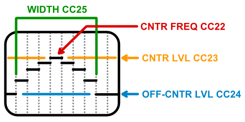
- patch 1:PSUEDO-PARAMETRIC: An imitation of parametric behavior which uses the same Controller and Note On velocity options as above, but processes them differently:
- cc22:center band: The center frequency of the peak/notch.
- cc23:center level: The level of the center frequency. If it is a higher value than off-center level there will be a band-pass effect, if lower there will be a band-block or “notch” effect.
- cc24:off-center level: The level of the furthest off-center frequencies outside of the width parameter.
- cc25:width: The width of the parametric curve effect, or number of bands above & below the center frequency.
- patch 10-19:USER PATCH 0-9: Storing user patches is discussed below. Once a patch is in memory it can be recalled by sending the Zeta Reticuli a MIDI patch change message for patches 10 through 19 (user patch # plus 10). Only the mode and associated EQ parameters are stored. None of the parameters for controllers associated with an expansion board are stored.
B. Other Controls
- cc6:gain level: Controls input level to preamp. See Input and Preamp below
- cc7:volume level: Controls output level. See Output below
C. Storing User Patches
As with everything else in the Zeta Reticuli there is more than one way to do this to accommodate different equipment and usage possibilities.
- The first way of storing a user program to memory is by using MIDI continuous controllers 70 through 79, sending a value of greater than 64. The controller to use for a specific user memory location is just 70 plus the number of the memory slot. Slot 0 is MIDI cc 70, slot 1 is 71, and so on. When the Zeta Reticuli receives one of these controller messages it stores all of the EQ parameters to the appropriate EEPROM addresses. As noted above, only the mode and associated EQ parameters are stored. None of the parameters for controllers associated with an expansion board are stored.
- The second way to store user patch data is through MIDI SysEx messages. This may be more complicated, but more convenient – at least in my case. A 7 byte SysEx message that will cause the Zeta Reticuli to store the current EQ settings to a specified user patch is as follows:
SysEx 'store user patch' message BYTE # DESCRIPTION HEX (DEC) NOTES 0 Begin 0xF0 (240) 1 Manufacturer 0x60 (96) 2 Model 0x0D (13) 3 Device ID 0x00 [not yet implemented] 4 Command 0x10 (16) store user patch command 5 Patch num 0x?? (??) 1 byte – use patch number (ie: the first user patch is 10) 6 End 0xF7 (247) - The Zeta Reticuli’s SysEx implementation allows it to also get patch data both to and from external software such as a MIDI librarian. This will only work over the USB port since there is no standard MIDI out port on the device. The format to retrieve a user patch over USB is exactly the same as above with the exception of byte 4 Command. This byte will need to be 0x11 (dec 17) in this instance, to signify a user patch request command. As soon as the Zeta Reticuli receives a properly formatted SysEx request it will respond over USB with an 18 byte reply:
SysEx 'user patch data' message BYTE # DESCRIPTION HEX (DEC) NOTES 0 Begin 0xF0 (240) 1 Manufacturer 0x60 (96) 2 Model 0x0D (13) 3 Device ID 0x00 [not yet implemented] 4 Command 0x12 (18) indicates that this is a 'transmit patch reply' 5 Patch num 0x?? (??) 1 byte – use patch number (ie: the first user patch is 10) 6 Mode 0x?? (??) Patch Data: mode. 1 byte. 0: Direct/1: Pseudo-parametric 7-16 Data 0x?? (??) Patch Data: all other parameters. 10 bytes. 17 End 0xF7 (247) - Power: 5VDC is brought in from a wall wart through a barrel connector.
- CPU: The Teensy. I love these lil guys! I started using them both because of cost and because their on-board USB (NOT FTDI) allows using various USB profiles natively, thus not having to do any fancy driver/emulator footwork. This IS a plug’n’play Arduino MIDI device.
- User interface: The Teensy sends display data to an HD44780-compatible LCD in 4-bit mode and takes input from two tactile push buttons. The push buttons choose which MIDI channel the Zeta Reticuli responds to MIDI input from. The LCD screen displays the current channel, level of each of the 10 EQ channels, and the current operating mode.
In this version of the circuit I have all 16 pins for the LCD pushing out on one header and a second 4 pin header taking 5v +/- out to the push buttons and returning the two inputs for the Teensy. After ordering the PCBs I quickly kicked myself realizing that I didn’t need that many lines as some are redundant and some are unused. This has been changed in the next version. - MIDI data: Input from (most of my) MIDI gear comes through the standard 5 pin DIN connector. I used a PCB-mount on the first version of this board, but will almost definitely use a panel-mount connected to a 90 degree header on the next version to free up board space as well as make enclosure layout more flexible. This data is isolated from the Teensy by an H11 optocoupler which I also robbed from the old MIDI interface.
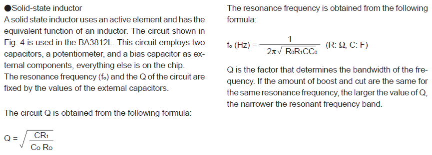
The current firmware allows for simultaneous MIDI to be received over the USB port. Theoretically you could add a MIDI out port and send and receive over the USB and MIDI ports, using it as a rudimentary MIDI-to-USB adapter. I plan on exploring this option in future versions, though I fear that timing and lag will be a serious issue. - Equalizer: The EQ section is based around (2) Rohm BA3812L chips. Honestly it’s just taken directly from the 10-band app note in the datasheet. The basic premise is that each frequency band is set by two capacitors. The first (A) sets the resonant (targeted) frequency and the second sets it’s bandwidth (Q). The datasheet has the formula for determining these values. The values and their resulting frequency bands that I used are listed below. Once a frequency band is isolated from the rest of the signal in this way a potentiometer is used to vary it’s volume before it is recombined with the rest of the signal and set out through the 1/4 inch jack output. The AD5206 chips (6 10k digital potentiometers) are used instead of standard pots so they can be controlled over SPI by the Teensy.
- Input and Preamp: Audio input enters through a 1/4 inch jack and is routed into one of the 10K digital pots which is controlled by MIDI continuous controller 6. I call this the “gain level” as this moderates the input through an LM386 circuit to boost the signal. Before deciding on using a preamp stage, while developing the circuit in a breadboard form it worked beautifully as long as I had a distortion pedal hooked before the Zeta Reticuli spaghetti. A clean signal just wasn’t up to driving it. This version of the PCB has the option to solder a cap across the opamp pins 1 and 8 to have a gain of 200. Without the cap the preamp has a gain of 20. The additional gain creates a lot of distortion, so in reality I am instead using a toggle to switch the chaos in and out. In the next version I plan to use a 3-position switch for preamp bypass/low/high levels. Even better would be a relay controlled by the Teensy so the options could be selected over MIDI.
- Output: Also routed into one of the 10K digital pots which is controlled by MIDI continuous controller 7 and referred to as “volume level”. I’m unsure if my separate use of controllers 6 and 7 could be problematic in some situations since, if I’m understanding their intended use correctly, are meant to be able to be combined together allowing a single 14 bit volume level.
- The Teensy is positioned behind the MIDI connector in a way that blocks any normal micro-USB connector. I was able to get a reliable connection by bending one of my cables’ connector. A 90-degree connector is definitely called for in this layout. Better yet, and what I’ve done, is use a panel-mount MIDI connector.
- I couldn’t find a pre-made library for the AD5206 digital potentiometer chips, so I made one. I had changed the grid size in Eagle and had forgotten which means that the width between rows of pins is way wrong. I was able to bend the pins and make it fit though, so no harm there.
- The MIDI DIN socket that I snatched off an old Mac MIDI interface has slightly different spacing on the 2 front mounting tabs than the Eagle library component I used. I neutered the one I used so it would fit. As mentioned above, I ended up removing the PCB-mount MIDI connector all together, replacing it with a panel-mount.
- The worst and most embarrassing mistake is that I got the power connector wrong. So so soooo wrong. This means that instead of the through-hole connector that I wanted I’m making do by using a panel-mount connector that doesn’t care how bad I messed up in the past as long as I hook it up correctly in the present.
D. Controlling Additional Effects
No point having idle pins, so I’m putting them to use extending the control capabilities through an 8 pin header. The header pipes the 5 volts, the 2 signals necessary for SPI (SCLK & MOSI), and enough chip select lines to control 4 more 5206 chips installed on expansion boards. The expansion board could be an individual stand-alone effect, which is the way I’m planning to implement an analog wah. It could also be just some pots accessed through a header to control an existing external effect that has been modded to be controlled by the Zeta Reticuli, which I’ve breadboarded using a cheap chorus pedal with great success.
Other SPI-controlled chips could be used in an expansion board, such as digital outputs to control relays for an MIDI controlled automatic signal router (Another plan in the works!), but the firmware would likely need changed to handle this. Another option that I’m considering is an SPI multiplexer to drastically increase the number of available CS lines. At this point the number of MIDI continuous controllers may then be the bottleneck and mapping multiple MIDI channels may be required. I’ve mentally bookmarked these and other options but to be real I haven’t even finished the updated version of this controller yet, let alone sketched out the first expansion board.
III. The First Version
A. Circuit
1. Sections
2. Frequencies and Capacitor values
| FREQ | CAP A | CAP B |
|---|---|---|
| 33Hz | 3.3µF | 0.082µF |
| 56Hz | 2.2µF | 0.047µF |
| 100Hz | 1µF | 0.022µF |
| 250Hz | 0.47µF | 10000pF |
| 500Hz | 0.22µF | 5600pF |
| 1kHz | 0.1µF | 2700pF |
| 2.2kHz | 0.068µF | 1000pF |
| 4.1kHz | 0.027µF | 680pF |
| 8.2kHz | 0.015µF | 330pF |
| 16kHz | 6800pF | 180pF |
While researching my project I also found a similar, albeit manually adjusted, kit that has some great info in its instructions PDF including many pre-calculated capacitor values.
3. Schematic
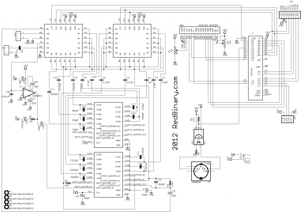
The schematic pictured here is the first version. The only correction or change is the pinout for the power connector.
| DESCRIPTION | VENDOR | VENDOR # | UNIT PRICE | COUNT | SUBTOTAL |
|---|---|---|---|---|---|
| EQ chip | eBay | Rohm BA3812L | $2.50 | 2 | $5.00 |
| digital pots | digikey | AD5206BN100-ND | $4.37 | 2 | $8.73 |
| teensy 2.0 | PJRC.com | TEENSY | $16.00 | 1 | $16.00 |
| LCD | eBay | HD44780-compatible | $5.00 | 1 | $5.00 |
| MIDI port | digikey | CP-2350-ND | $0.81 | 1 | $0.81 |
| 1/4 jacks | digikey | SC1121-ND | $1.98 | 2 | $3.96 |
| optocoupler | digikey | H11L1-MQT-ND | $0.91 | 1 | $0.91 |
| power jack | 1 | $0.00 | |||
| CAP 680PF | digikey | 445-4736-ND | $0.23 | 1 | $0.23 |
| CAP 5600PF | digikey | 445-8391-ND | $0.27 | 1 | $0.27 |
| CAP 6800PF | digikey | 445-8392-ND | $0.27 | 1 | $0.27 |
| CAP 0.015µF | digikey | 445-8279-ND | $0.33 | 1 | $0.33 |
| CAP 0.022µF | digikey | 445-8280-ND | $0.46 | 1 | $0.46 |
| CAP 330PF | digikey | 445-4777-ND | $0.23 | 1 | $0.23 |
| CAP 180PF | digikey | 445-4774-ND | $0.20 | 1 | $0.20 |
| CAP 2700PF | digikey | 445-4788-ND | $0.23 | 1 | $0.23 |
| CAP 10000PF | digikey | 445-8384-ND | $0.20 | 1 | $0.20 |
| CAP 0.1µF | digikey | 445-8421-ND | $0.20 | 1 | $0.20 |
| CAP 0.47µF | digikey | 445-8413-ND | $0.23 | 1 | $0.23 |
| CAP 1µF | digikey | 445-8405-ND | $0.27 | 1 | $0.27 |
| CAP 3.3µF | digikey | 445-8294-ND | $0.33 | 1 | $0.33 |
| CAP 1000PF | digikey | 445-4783-ND | $0.23 | 3 | $0.70 |
| CAP 0.027µF | digikey | P4649-ND | $0.21 | 1 | $0.21 |
| CAP 0.082µF | digikey | P4724-ND | $0.22 | 1 | $0.22 |
| CAP 0.22µF | digikey | 445-5311-ND | $0.27 | 1 | $0.27 |
| CAP 0.047µF | digikey | 445-5301-ND | $0.20 | 2 | $0.40 |
| CAP 0.068µF | digikey | P4523-ND | $0.28 | 1 | $0.28 |
| CAP 2.2µF | digikey | 445-8298-ND | $0.33 | 1 | $0.33 |
| CAP 100µF | digikey | 399-6602-ND | $0.11 | 2 | $0.22 |
| CAP 10µF | digikey | 399-6597-ND | $0.10 | 2 | $0.20 |
| RES 6.8K | digikey | 6.8KEBK-ND | $0.03 | 2 | $0.06 |
| OPAMP | digikey | LM386N-1/NOPB-ND | $0.93 | 1 | $0.93 |
| POT 10K | digikey | 262UR103B-ND | $0.69 | 2 | $1.38 |
| RES 10K | digikey | 10KQBK-ND | $0.07 | 1 | $0.07 |
| RES 220 | digikey | 220QBK-ND | $0.07 | 1 | $0.07 |
| RES 270 | digikey | 270QBK-ND | $0.07 | 1 | $0.07 |
| Breakaway headers | digikey | S1012EC-40-ND | $0.51 | 1 | $0.51 |
| TOTAL | $49.76 |
B. PCB
The first draft of this is also the first PCB I’ve ever had professionally manufactured. This has been a bucketlist-level dream that has intimidated me for years and finally going all in on it, despite my mistakes, has been very eye opening.
At the recommendation of a friend I used ITead Studio to make them and I am turbo-happy with the job they did as well as the cost. It took about a month to get the boards back. The vast majority of that time was the shipping. Even before they arrived I had already made a number of changes to the design. Once they were in hand I found that I had also made several rookie mistakes as well:
C. Firmware
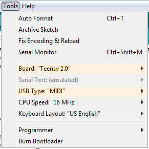
The firmware is very much a work in progress. If you are using a Teensy for the first time be sure to first follow the Getting Started guide from PJRC.com and that all of the appropriate software is installed. When using the Arduino IDE make sure that in the Tools menu that Board is set to “Teensy 2.0” and USB Type is set to “MIDI”.
|
1 2 3 4 5 6 7 8 9 10 11 12 13 14 15 16 17 18 19 20 21 22 23 24 25 26 27 28 29 30 31 32 33 34 35 36 37 38 39 40 41 42 43 44 45 46 47 48 49 50 51 52 53 54 55 56 57 58 59 60 61 62 63 64 65 66 67 68 69 70 71 72 73 74 75 76 77 78 79 80 81 82 83 84 85 86 87 88 89 90 91 92 93 94 95 96 97 98 99 100 101 102 103 104 105 106 107 108 109 110 111 112 113 114 115 116 117 118 119 120 121 122 123 124 125 126 127 128 129 130 131 132 133 134 135 136 137 138 139 140 141 142 143 144 145 146 147 148 149 150 151 152 153 154 155 156 157 158 159 160 161 162 163 164 165 166 167 168 169 170 171 172 173 174 175 176 177 178 179 180 181 182 183 184 185 186 187 188 189 190 191 192 193 194 195 196 197 198 199 200 201 202 203 204 205 206 207 208 209 210 211 212 213 214 215 216 217 218 219 220 221 222 223 224 225 226 227 228 229 230 231 232 233 234 235 236 237 238 239 240 241 242 243 244 245 246 247 248 249 250 251 252 253 254 255 256 257 258 259 260 261 262 263 264 265 266 267 268 269 270 271 272 273 274 275 276 277 278 279 280 281 282 283 284 285 286 287 288 289 290 291 292 293 294 295 296 297 298 299 300 301 302 303 304 305 306 307 308 309 310 311 312 313 314 315 316 317 318 319 320 321 322 323 324 325 326 327 328 329 330 331 332 333 334 335 336 337 338 339 340 341 342 343 344 345 346 347 348 349 350 351 352 353 354 355 356 357 358 359 360 361 362 363 364 365 366 367 368 369 370 371 372 373 374 375 376 377 378 379 380 381 382 383 384 385 386 387 388 389 390 391 392 393 394 395 396 397 398 399 400 401 402 403 404 405 406 407 408 409 410 411 412 413 414 415 416 417 418 419 420 421 422 423 424 425 426 427 428 429 430 431 432 433 434 435 436 437 438 439 440 441 442 443 444 445 446 447 448 449 450 451 452 453 454 455 456 457 458 459 460 461 462 463 464 465 466 467 468 469 470 471 472 473 474 475 476 477 478 479 480 481 482 483 484 485 486 487 488 489 490 491 492 493 494 495 496 497 498 499 500 501 502 503 504 505 506 507 508 509 510 511 512 513 514 515 516 517 518 519 520 521 522 523 524 525 526 527 528 529 530 531 532 533 534 535 536 537 538 539 540 541 542 543 544 545 546 547 548 549 550 551 552 553 554 555 556 557 558 559 560 561 562 563 564 565 566 567 568 569 570 571 572 573 574 575 576 577 578 579 580 581 582 583 584 585 586 587 588 589 590 591 592 593 594 595 596 597 598 599 600 601 602 603 604 605 606 607 608 609 610 611 612 613 614 615 616 617 618 619 620 621 622 |
/******************************************************************************************************************************** ZETA RETICULI MIDI EQ CONTROLLER 2012 PATRICK GRIFFIN/REDBINARY.COM CURVE MODES: selected using program change PATCH 0: direct levels CC#HEX CC#DEC BANK/ADDR FUNCTION ====== ====== ========= ======================================== PATCH 0: direct levels 16 22 0/0 freq 1 17 23 0/1 freq 2 18 24 0/2 freq 3 19 25 0/3 freq 4 1A 26 0/4 freq 5 1B 27 0/5 freq 6 1C 28 1/0 freq 7 1D 29 1/1 freq 8 1E 30 1/2 freq 9 1F 31 1/3 freq 10 PATCH 1: pseudo-parametric 16 22 0/0 target center band 17 23 0/1 curve_max (height of target) 18 24 0/2 curve_min (depth of off-target) 19 25 0/3 curve_width (number of steps to roll-off from target to min) 20 26 0/4 curve_slope PATCH 2: note triggers note numbers 60-69 are bands, velocity is level USER MEMORIES: 0 - 9 written using cc 70-79 (&h46-4F), selected using program change 10-19 memory format: byte # descr info ====== ===== ====================================================== b00 type 0 = static/direct levels, 1 = dynamic/pseudo-parametric b01 (direct)level01 / (pseudo-parametric)initial target b02 (direct)level02 / (pseudo-parametric)target level b03 (direct)level03 / (pseudo-parametric)off-target level b04 (direct)level04 / (pseudo-parametric)width b05 (direct)level05 b06 (direct)level06 b07 (direct)level07 b08 (direct)level08 b09 (direct)level09 b10 (direct)level10 ********************************************************************************************************************************/ #include #include #include #include #include #include #define LED 11 #define BANK_ADDRESSES 6 #define BAND_COUNT 10 #define CURVE_MAX 255 #define CURVE_MIN 0 #define CURVE_WIDTH 10 //(BAND_COUNT * 2) #define CURVE_DEFAULT 127 #define PIN_INC 16 #define PIN_DEC 17 #define DEBOUNCE_DELAY 20 #define ADDR_CHANNEL 0 #define ADDR_MODE 1 #define MODE_MAX 1 #define BASE_USER_ADDR 9 #define USER_PATCH_SIZE 11 #define ADDR_MEM00 9 #define ADDR_MEM01 9 #define ADDR_MEM02 9 #define ADDR_MEM03 9 #define ADDR_MEM04 9 #define ADDR_MEM05 9 #define ADDR_MEM06 9 #define ADDR_MEM07 9 #define ADDR_MEM08 9 #define ADDR_MEM09 9 #define PROG_DIRECT 0 #define PROG_PARAMETRIC 1 //#define PROG_NOTE_DIRECT 2 //#define PROG_NOTE_PARAMETRIC 3 #define PROG_MEMORY0 10 #define PROG_MEMORY1 11 #define PROG_MEMORY2 12 #define PROG_MEMORY3 13 #define PROG_MEMORY4 14 #define PROG_MEMORY5 15 #define PROG_MEMORY6 16 #define PROG_MEMORY7 17 #define PROG_MEMORY8 18 #define PROG_MEMORY9 19 const int write_mem_cc[] = { 70, 71, 72, 73, 74, 75, 76, 77, 78, 79 }; // continuous controllers for writing user patches const int addr_mem[] = { 9, 20, 31, 42, 53, 64, 75, 86, 97, 108 }; // eeprom addresses for user patches #define CC_GAIN 6 // cc# for gain #define CC_VOLUME 7 // cc# for volume #define ADDR_GAIN 10 // spi address for gain #define ADDR_VOLUME 11 // spi address for volume int vol_value = 64; int gain_value = 64; LiquidCrystalFast lcd(9, 11, 10, 12, 13, 14, 15); // RS, RW, EN, D4, D5, D6, D7 const int pin_select_bank[] = { 0, 4 }; // which teensy pins select digital pot chips const int bank_count = 2; // # of pot chips int curve_mode;// = 1; int curve_width = 0; int curve_band = 0; boolean enable_note_ctrl = true; // whether or not notes can be used instead of or along with cc's boolean enable_as_adapter = false; // whether or not MIDI messages should be passed between standard & USB ports // initialize stored band values to default int band_value[] = { CURVE_DEFAULT, CURVE_DEFAULT, CURVE_DEFAULT, CURVE_DEFAULT, CURVE_DEFAULT, CURVE_DEFAULT, CURVE_DEFAULT, CURVE_DEFAULT, CURVE_DEFAULT, CURVE_DEFAULT }; // MIDI settings int midi_channel;// = 3; const int midi_controller_num[] = { 22, 23, 24, 25, 26, 27, 28, 29, 30, 31 }; // direct level mode controllers for freq bands // PARAMETRIC SETTINGS const int cc_affected_band = 22; // center freq const int cc_curve_max = 23; // const int cc_curve_min = 24; const int cc_curve_width = 25; int curve_max = CURVE_MAX; int curve_min = CURVE_MIN; // custom bar characters for LCD byte bar1[8] = { 0b00000, 0b00000, 0b00000, 0b00000, 0b00000, 0b00000, 0b00000, 0b11111 }; byte bar2[8] = { 0b00000, 0b00000, 0b00000, 0b00000, 0b00000, 0b00000, 0b11111, 0b00000 }; byte bar3[8] = { 0b00000, 0b00000, 0b00000, 0b00000, 0b00000, 0b11111, 0b00000, 0b00000 }; byte bar4[8] = { 0b00000, 0b00000, 0b00000, 0b00000, 0b11111, 0b00000, 0b00000, 0b00000 }; byte bar5[8] = { 0b00000, 0b00000, 0b00000, 0b11111, 0b00000, 0b00000, 0b00000, 0b00000 }; byte bar6[8] = { 0b00000, 0b00000, 0b11111, 0b00000, 0b00000, 0b00000, 0b00000, 0b00000 }; byte bar7[8] = { 0b00000, 0b11111, 0b00000, 0b00000, 0b00000, 0b00000, 0b00000, 0b00000 }; byte bar8[8] = { 0b11111, 0b00000, 0b00000, 0b00000, 0b00000, 0b00000, 0b00000, 0b00000 }; #define MODE_COL 11 // LCD column for mode description string #define MODE_ROW 1 // LCD row for same // LCD mode description strings const String mode_str[] = { "dir ", "par ", "usr" }; #define CH_COL 11 // LCD column for channel display string #define CH_ROW 0 // LCD row for same const String ch_str = "ch:"; // string to use on LCD for channel // set up debounce inputs Bounce bounce_inc = Bounce( PIN_INC, DEBOUNCE_DELAY ); boolean state_old_inc = false; Bounce bounce_dec = Bounce( PIN_DEC, DEBOUNCE_DELAY ); boolean state_old_dec = false; void setup() { // for debug Serial.begin(57600); for (int i = 0; i < BANK_ADDRESSES; i++) { pinMode(pin_select_bank[i], OUTPUT); } pinMode(PIN_INC, INPUT); pinMode(PIN_DEC, INPUT); midi_channel = EEPROM.read(ADDR_CHANNEL); if (midi_channel < 1 || midi_channel > 16) midi_channel = 8; curve_mode = EEPROM.read(ADDR_MODE); if (curve_mode < 0) curve_mode = 0; if (curve_mode > MODE_MAX) curve_mode = MODE_MAX; SPI.begin(); MIDI.begin(midi_channel); ResetAllBands(); lcd.begin(16, 2); // initialize the lcd // create char(0-7) array lcd.createChar (0, bar1); lcd.createChar (1, bar2); lcd.createChar (2, bar3); lcd.createChar (3, bar4); lcd.createChar (4, bar5); lcd.createChar (5, bar6); lcd.createChar (6, bar7); lcd.createChar (7, bar8); writeLCDmode(); writeLCDchannel(); writeCurve(); MIDI.turnThruOff(); } void loop() { int channel, d1, d2; int usb_channel, usb_d1, usb_d2; //HANDLE STANDARD MIDI PORT RECEIVED DATA if (MIDI.read()) { byte type = MIDI.getType(); d1 = MIDI.getData1(); d2 = MIDI.getData2(); channel = MIDI.getChannel(); byte * sysex_array = MIDI.getSysExArray(); if (channel == midi_channel || type == SystemExclusive) { switch (type) { case ControlChange: handleControlChange(d1, d2); break; case ProgramChange: handleProgramChange(d1); break; case SystemExclusive: handleSysEx(sysex_array, d1); break; case NoteOn: handleNoteOn(d1, d2); break; case NoteOff: handleNoteOff(d1); break; } } if (enable_as_adapter) { //pass MIDI to usbMIDI } } //HANDLE USB MIDI PORT RECEIVED DATA if (usbMIDI.read()) { byte usb_type = usbMIDI.getType(); usb_d1 = usbMIDI.getData1(); usb_d2 = usbMIDI.getData2(); usb_channel = usbMIDI.getChannel(); byte * usb_sysex_array = usbMIDI.getSysExArray(); if (usb_channel == midi_channel || usb_type == SystemExclusive) { switch (usb_type) { case ControlChange: handleControlChange(usb_d1, usb_d2); break; case ProgramChange: handleProgramChange(usb_d1); break; case SystemExclusive: handleSysEx(usb_sysex_array, usb_d1); break; case NoteOn: handleNoteOn(usb_d1, usb_d2); break; case NoteOff: handleNoteOff(usb_d1); break; } } if (enable_as_adapter) { //pass usbMIDI to MIDI } } // HANDLE BUTTONS // increment button bounce_inc.update(); boolean state_inc = bounce_inc.read(); if (state_old_inc != state_inc && state_inc == HIGH) { midi_channel++; if (midi_channel > 16) midi_channel = 1; MIDI.begin(midi_channel); //usbMIDI.begin(midi_channel); writeLCDchannel(); } state_old_inc = state_inc; // decrement button bounce_dec.update(); boolean state_dec = bounce_dec.read(); if (state_old_dec != state_dec && state_dec == HIGH) { midi_channel--; if (midi_channel < 1) midi_channel = 16; MIDI.begin(midi_channel); //usbMIDI.begin(midi_channel); writeLCDchannel(); } state_old_dec = state_dec; } void handleSysEx() { } void digitalPotWrite(int address, int value) { // determine which bank address is in int bank = 0; if (address > (BANK_ADDRESSES - 1)) { address = address - BANK_ADDRESSES; bank = 1; } // take the SS pin for selected bank low to select the chip: digitalWrite(pin_select_bank[bank], LOW); // send in the address and value via SPI: SPI.transfer(address); SPI.transfer(value); // take the SS pin high to de-select the chip: digitalWrite(pin_select_bank[bank], HIGH); } void writeCurve() { for (int band = 0; band < BAND_COUNT; band++) { digitalPotWrite(band, band_value[band]); writeLCDband(band, band_value[band]); } } void writeVolume(int new_volume) { digitalPotWrite(ADDR_VOLUME, new_volume); } void writeGain(int new_gain) { digitalPotWrite(ADDR_GAIN, new_gain); } void writeLCDband(int address, int value) { int row = 1; int adj_val = value; if (value > 127) { row = 0; value -= 127; lcd.setCursor( address, 1 ); lcd.print(" "); } else { lcd.setCursor( address, 0 ); lcd.print(" "); } adj_val = (value / 15) + 1; if (adj_val < 0) adj_val = 0; if (adj_val > 7) adj_val = 7; lcd.setCursor( address, row ); lcd.print(char(adj_val)); } void writeLCDmode() { EEPROM.write(ADDR_MODE, curve_mode); lcd.setCursor( MODE_COL, MODE_ROW ); lcd.print(mode_str[curve_mode]); } void writeLCDchannel() { EEPROM.write(ADDR_CHANNEL, midi_channel); lcd.setCursor( CH_COL, CH_ROW ); lcd.print(" "); lcd.setCursor( CH_COL, CH_ROW ); lcd.print(ch_str + String(midi_channel)); } void handleControlChange(int control, int value) { if (control >= write_mem_cc[0] && control <= write_mem_cc[9] && value > 63) { // handle one of the on/off cc's wanting to write a user patch int mem_index = control - write_mem_cc[0]; WriteMemorySet(mem_index + 2); } else if (control == CC_VOLUME) { vol_value = value * 2; writeVolume(value); } else if (control == CC_GAIN) { gain_value = value * 2; writeGain(value); } else { if (curve_mode == PROG_DIRECT) { // DIRECT LEVELS if (control >= midi_controller_num[0] && control <= midi_controller_num[BAND_COUNT - 1]) { // initial boundary check for cc# being valid for a freq band int band_index = control - midi_controller_num[0]; if (band_index > -1 && band_index < BAND_COUNT) { // redundant boundary check int scaled_value = value * 2; if (scaled_value < curve_min) scaled_value = curve_min; if (scaled_value > curve_max) scaled_value = curve_max; band_value[band_index] = scaled_value; digitalPotWrite(band_index, band_value[band_index]); writeLCDband(band_index, band_value[band_index]); } } } else if (curve_mode == PROG_PARAMETRIC) { // PSEUDO-PARAMETRIC if (control == cc_affected_band) { // identify affected band curve_band = 0; int divisor = 127 / BAND_COUNT; if (value > 0 && divisor > 0) { curve_band = value / divisor; } if (curve_band >= BAND_COUNT) curve_band = BAND_COUNT - 1; CalcParametricBands(); writeCurve(); } else if (control == cc_curve_min) { curve_min = value * 2; CalcParametricBands(); writeCurve(); } else if (control == cc_curve_max) { curve_max = value * 2; CalcParametricBands(); writeCurve(); } else if (control == cc_curve_width) { int divisor = 127 / (BAND_COUNT * 2); if (value > 0 && divisor > 0) { curve_width = value / divisor; } if (curve_width >= (BAND_COUNT * 2)) curve_width = (BAND_COUNT * 2) - 1; CalcParametricBands(); writeCurve(); } } } } void handleProgramChange(byte program) { if (program <= PROG_MEMORY9) { if (program == PROG_DIRECT) { curve_mode = program; curve_min = CURVE_MIN; curve_max = CURVE_MAX; ResetAllBands(); } else if (program == PROG_PARAMETRIC) { curve_mode = program; ResetAllBands(); } else if (program >= PROG_MEMORY0) { ReadMemorySet(program); } writeCurve(); writeLCDmode(); } } // SYSEX DATA CAN BE RECEIVED ON EITHER STANDARD OR USB PORT BUT CAN ONLY BE TRANSMITTED OVER USB void handleSysEx(byte * rcvd_array, int array_len) { /* [0] Begin - 0xF0 (240) [1] Manufacturer - 0x60 (96) [2] Model - 0x0D (13) [3] Device ID - 0x00 [not yet implemented] [4] Command - 0x10 (16) (store user patch) 0x11 (17) (request patch) [5] Patch num - 1 byte [6] End - 0xf7 (247) */ if (array_len == 7) { // correct size for patch data request if (rcvd_array[0] == 0xf0 && rcvd_array[6] == 0xf7) { //correctly framed if (rcvd_array[1] == 0x60 && rcvd_array[2] == 0x0D) { // correct OEM && model if (rcvd_array[4] == 0x11) { //request patch command sysExTransmitPatch((int) rcvd_array[5]); } else if (rcvd_array[4] == 0x10) { //store user patch command WriteMemorySet(rcvd_array[5]); } } } } } void handleNoteOn(int note, int vel) { if (enable_note_ctrl == true) { int val = (note - 60) * BAND_COUNT; handleControlChange(cc_affected_band, val); // map note on to controller } } void handleNoteOff(int note) { /*if (curve_mode == PROG_NOTE_DIRECT && note >= 60 && note <= 69) { int target_band = note - 60; //Serial.println( String("NoteOff: ") + note ); band_value[target_band] = 0; digitalPotWrite(target_band, band_value[target_band]); writeLCDband(target_band, band_value[target_band]); }*/ } void ReadMemorySet(byte patch) { int patch_index = patch - 10; int base_addr = addr_mem[patch_index]; curve_mode = EEPROM.read(base_addr); if (curve_mode == PROG_DIRECT) { for (int band_i = 0; band_i < BAND_COUNT; band_i++) { band_value[band_i] = EEPROM.read(base_addr + 1 + band_i); } } else if (curve_mode == PROG_PARAMETRIC) { curve_band = EEPROM.read(base_addr + 1); curve_max = EEPROM.read(base_addr + 2); curve_min = EEPROM.read(base_addr + 3); curve_width = EEPROM.read(base_addr + 4); } } void WriteMemorySet(byte index) { int base_addr = addr_mem[index]; EEPROM.write(base_addr, curve_mode); if (curve_mode == PROG_DIRECT) { for (int band_i = 0; band_i < BAND_COUNT; band_i++) { EEPROM.write(base_addr + 1 + band_i, band_value[band_i]); } } else if (curve_mode == PROG_PARAMETRIC) { EEPROM.write(base_addr + 1, curve_band); EEPROM.write(base_addr + 2, curve_max); EEPROM.write(base_addr + 3, curve_min); EEPROM.write(base_addr + 4, curve_width); } } void ResetAllBands() { for (int band_reset = 0; band_reset < BAND_COUNT; band_reset++) { band_value[band_reset] = CURVE_DEFAULT; } } void CalcParametricBands() { int band_lo = 0; int band_hi = 0; int inc = 0; if (curve_width > 0) { band_lo = curve_band - curve_width; if (band_lo < 0) band_lo = 0; band_hi = curve_band + curve_width; if (band_hi > (BAND_COUNT - 1)) band_hi = BAND_COUNT - 1; inc = (curve_max - curve_min) / curve_width; } // write affected to max, others to min for (int i = 0; i < BAND_COUNT; i++) { if (i == curve_band) { band_value[i] = curve_max; } else if (curve_width > 0 && i >= band_lo && i <= band_hi) { // inside affected range int offset = abs(curve_band - i); band_value[i] = curve_max - (inc * offset); } else { band_value[i] = curve_min; } } } void sysExTransmitPatch(int pPatch) { int patch_index = pPatch - 10; int base_addr = patch_index * USER_PATCH_SIZE + BASE_USER_ADDR; int pCurve_mode = EEPROM.read(base_addr); byte d[] = { 0, 0, 0, 0, 0, 0, 0, 0, 0, 0 }; if (pCurve_mode == PROG_DIRECT) { for (int band_i = 0; band_i < BAND_COUNT; band_i++) { band_value[band_i] = EEPROM.read(base_addr + 1 + band_i); d[band_i] = (byte) band_value[band_i]; } } else if (pCurve_mode == PROG_PARAMETRIC) { int pCurve_band = EEPROM.read(base_addr + 1); int pCurve_max = EEPROM.read(base_addr + 2); int pCurve_min = EEPROM.read(base_addr + 3); int pCurve_width = EEPROM.read(base_addr + 4); d[0] = pCurve_band; d[1] = pCurve_max; d[2] = pCurve_min; d[3] = pCurve_width; } /* Begin - 0xF0 Manufacturer - 0x60 (96) Model - 0x0D (13) Device ID - 0x00 [not yet implemented] Command - 0x12 (transmit patch) Patch num - 1 byte Patch Data: curve mode - 1 byte curve data - 10 bytes End - 0xf7 */ byte xmit_string[] = { 0xf0, 0x60, 0x0d, 0x00, 0x12, (byte) patch_index, (byte) pCurve_mode, d[0], d[1], d[2], d[3], d[4], d[5], d[6], d[7], d[8], d[9], 0xf7 }; delay(250); usbMIDI.sendSysEx( 18, xmit_string); } void sysExReceivePatch(int pPatch) { //TODO } |
IV. First Version Enclosure
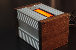
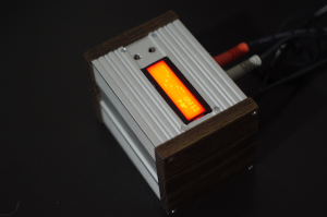
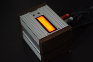
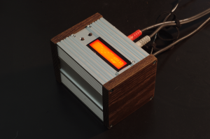
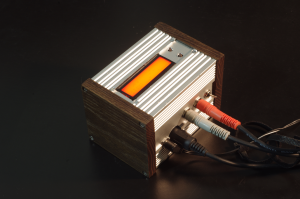
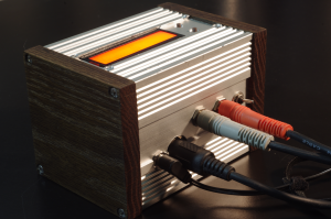
I struggled with the design of the first enclosure for this. I was putting so much weight on the the appearance and durability (and still am, if I’m being honest) that I was almost frozen. While I am somewhat happy with the way this particular enclosure has turned out, I really don’t feel like it is it’s final incarnation. Aside from the base design aesthetic, I’m not super happy with the alignment of everything and there are some obvious places where I filed unevenly. I’ll likely make another of this exact enclosure just to prove to myself I can get it right and then start making others of different designs until I hit on the design that completely satisfies me.
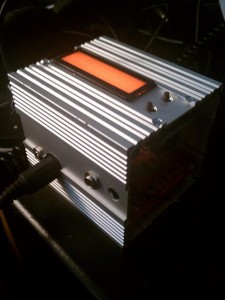
The original idea was to capture some of what I feel looking at both vintage home stereo equipment from the 60’s/70’s and vintage synth equipment. We have some SAE home audio gear from the 1970’s in our home that I really appreciate the look of. They’re rack mountable, but if you don’t want to mount them in 19-inch racks they have an additional enclosure with wooden sides that the equipment will mount in just like an ornamental single-unit 19-inch rack. After several frustrations first cutting then bending the metal I decided to go a different route until I can revisit that design with more focus on building up the needed tools beforehand. This particular enclosure is made from the coated aluminum case of an old temperature controller from my work.
I still wanted the wooden sides. I toyed with ideas for more rectangular, and even triangular, ends. I ended up starting out with very simple plain ends so that I would get a bit more insight into what I was dealing with. When I remake the case I will most likely try making something with built-in cable routing.
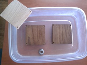
One thing that was always certain and unwavering was that I would be ammonia staining the wooden parts. If you have never used this method I would highly recommend trying it out. I’ve refinished many things using this technique and developed my own twist on it. In my opinion there is nothing that matches the depth and intricacy of it. It’s very simple, works on about any hardwood, and is a relatively slow process which can take up to 48 hours to complete a dark piece. This means you can stop it at exactly the level of stain you want. Personally, I especially like it dark on oak and walnut.
My process is very simple. Once the piece is ready to be stained I rub it with 2 or 3 coats of linseed oil, letting them dry out in between. This first oiling step really adds depth and seems to accelerate the process as well. You will need to have an airtight place to let the fumigatory staining process happen. This can be a trash bag framed out with scrap wood or, as in this case, a Tupperware-type container. Just make sure it’s airtight so the ammonia doesn’t evaporate away and leave the area smelling like a meth lab. For large pieces it may be beneficial to rig up a small case fan or some other way to get the air to circulate inside the ‘tent’ so that the bottom doesn’t stain faster than the top. After the last coat of linseed oil, dry or not, I put a random, unmeasured amount of ammonia in the ‘fume tent’ and space the article up out of the ammonia. In the Tupperware I had the case ends sitting on wingnuts. You should try to keep the contact area between the piece and it’s spacers as small as possible. The points of contact will receive less ammonia and may show lighter. For this reason it’s also not a bad idea to reposition the piece on the spacers every few hours.
 |
 |
|
|---|---|---|
 |
 |
 |
V. Examples
2012-12-07: Since completing the Zeta Reticuli a couple of weeks ago (at the time this post was made) I have been obsessed with making a better enclosure for it. I failed hard & it’s kept me from actually having time to play with it in it’s intended capacity. I took a short break from mundane tasks today to spend a couple of minutes making a video showing, in my inept way, a simple use-case scenario.
A quick demo I made of the Zeta Reticuli MIDI EQ running a short, looped pattern. Again, I’m strumming one chord. The guitar is plugged directly into the Reticuli with “chaos gain” switched on. The Reticuli is plugged into a small Marshall amp with it’s gain turned all the way up as well. Sound was recorded by the camera, so is not the best. Not that it needs to be.
2012-12-13: I added an oscillator for the pseudo-parametric mode in the firmware. I’ll make an update post soon, but in the meantime here is video of the Zeta Reticuli manipulating raw guitar feedback with it’s new oscillator settings. It’s in it’s temporary “fail case” and I’m using a separate interface I made with a second Teensy to control the Zeta.
Testing the new oscillator firmware with guitar feedback. I made a separate MIDI controller for the Zeta so I would have portable hands-on control of each setting.
Also here’s a clip of a better recording of a short keyboard loop being manipulated by the Zeta, as well:
A very short sequencer loop on a Korg Poly800 straight into the Zeta Reticuli MIDI EQ then straight into a PC to demonstrate the new oscillator controls. No audio processing whatsoever was done outside of the Zeta Reticuli.
VI. The Second Version
Coming soon…
