Microchip PIC Serial LCD driver

As a gift for putting you through revamping my site, here are the particulars for a microchip pic serial LCD driver that I personally use in projects and used to sell commercially.
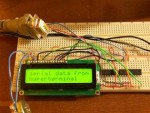
The SLD01a serial LCD driver design is a for a Microchip PIC 16F628a, but it should be simple to port over to any PIC with a USART. It converts serial data in either RS-232c or TTL formats to display on any Hitachi HD44780-compatible LCD. Applications include industrial/PLC control read-outs, microprocessor projects, computer mods, and anything else that uses serial data. It doesn’t have a lot of bells and whistles (but it DOES have a bell DRIVER) as some other drivers do. It’s designed to be a simple, light-weight terminal-style display.
To paraphrase the documentation sheet:
The SLD01a serial LCD driver will convert raw serial data into a 4-bit parallel format applicable to LCD displays which use a Hitachi HD44780-compatible character display chipset. A 64 byte receive buffer is used to assist in data loss prevention.
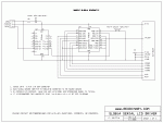
The SLD01a requires a 5vdc powersupply. Additional support circuitry is necessary to convert RS232C data signals to TTL if the SLD01a is intended for this purpose. A MAX232 or similar is typically all that is required, as shown in the sample schematic.
Serial data must be in format: 8-bit, no parity, 1 stop bit, and at the rate of 9600 bps. Any other settings will require editing the provided source.
When the non-text linefeed and carriage return characters are received the SLD01a will cause the LCD display cursor to move to the first character placement on the next line of the display. After the last character of the last line is reached the SLD01a will clear the display and begin again at the first character of the first line.
When the non-printable delete character is encountered, the SLD01a will delete the last displayed character.
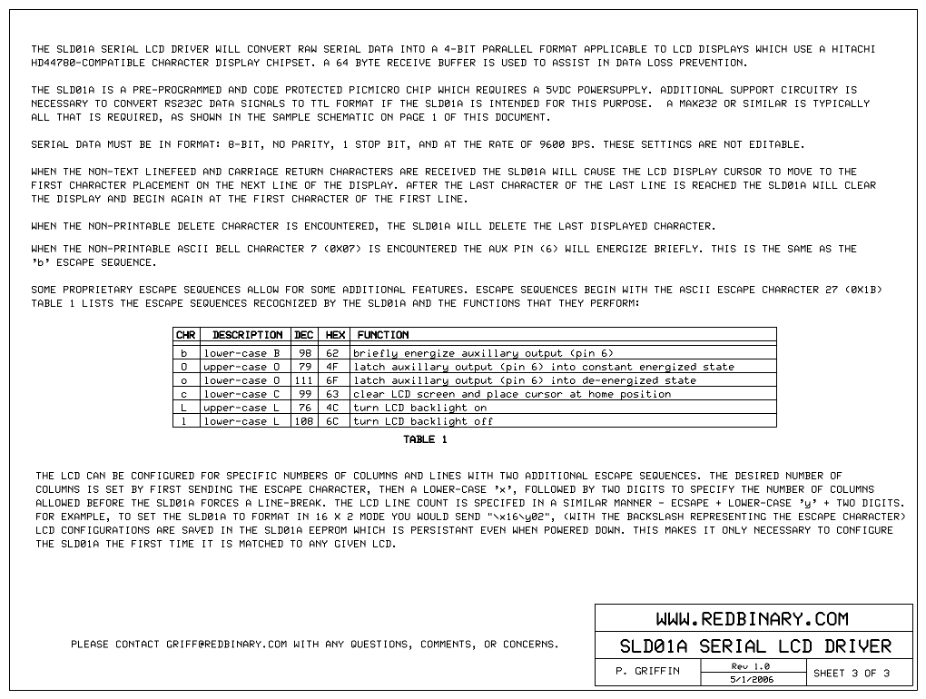
When the non-printable ASCII bell character 7 (0x07) is encountered the aux pin (6) will energize briefly. This is the same as the ‘b’ escape sequence.
Some proprietary escape sequences allow for some additional features. Escape sequences begin with the ASCII escape character 27 (0x1b) The table in sheet 3 below lists the escape sequences recognized by the SLD01a and the functions that they perform.
The LCD can be configured for specific numbers of columns and lines with two additional escape sequences. The desired number of columns is set by first sending the escape character, then a lower-case ‘x’, followed by two digits to specify the number of columns allowed before the SLD01a forces a line-break. The LCD line count is specifed in a similar manner – ecsape + lower-case ‘y’ + two digits. For example, to set the SLD01a to format in 16 x 2 mode you would send “\x16\y02”, (with the backslash representing the escape character) LCD configurations are saved in the SLD01a EEPROM which is persistant even when powered down. This makes it only necessary to configure the SLD01a the first time it is matched to any given LCD.


The code below was compiled using the CC5X compiler. Using another compiler will likely require compatibility tweaks. Do to several requests I am also making available for download the HEX file.
|
1 2 3 4 5 6 7 8 9 10 11 12 13 14 15 16 17 18 19 20 21 22 23 24 25 26 27 28 29 30 31 32 33 34 35 36 37 38 39 40 41 42 43 44 45 46 47 48 49 50 51 52 53 54 55 56 57 58 59 60 61 62 63 64 65 66 67 68 69 70 71 72 73 74 75 76 77 78 79 80 81 82 83 84 85 86 87 88 89 90 91 92 93 94 95 96 97 98 99 100 101 102 103 104 105 106 107 108 109 110 111 112 113 114 115 116 117 118 119 120 121 122 123 124 125 126 127 128 129 130 131 132 133 134 135 136 137 138 139 140 141 142 143 144 145 146 147 148 149 150 151 152 153 154 155 156 157 158 159 160 161 162 163 164 165 166 167 168 169 170 171 172 173 174 175 176 177 178 179 180 181 182 183 184 185 186 187 188 189 190 191 192 193 194 195 196 197 198 199 200 201 202 203 204 205 206 207 208 209 210 211 212 213 214 215 216 217 218 219 220 221 222 223 224 225 226 227 228 229 230 231 232 233 234 235 236 237 238 239 240 241 242 243 244 245 246 247 248 249 250 251 252 253 254 255 256 257 258 259 260 261 262 263 264 265 266 267 268 269 270 271 272 273 274 275 276 277 278 279 280 281 282 283 284 285 286 287 288 289 290 291 292 293 294 295 296 297 298 299 300 301 302 303 304 305 306 307 308 309 310 311 312 313 314 315 316 317 318 319 320 321 322 323 324 325 326 327 328 329 330 331 332 333 334 335 336 337 338 339 340 341 342 343 344 345 346 347 348 349 350 351 352 353 354 355 356 357 358 359 360 361 362 363 364 365 366 367 368 369 370 371 372 373 374 375 376 377 378 379 380 381 382 383 384 385 386 387 388 389 390 391 392 393 394 395 396 397 398 399 400 401 402 403 404 405 406 407 408 409 410 411 412 413 414 415 416 417 418 419 420 421 422 423 424 425 426 427 428 429 430 431 432 433 434 435 436 437 438 439 440 441 442 443 444 445 446 447 448 449 450 451 452 453 454 455 456 457 458 459 460 461 462 463 464 465 466 467 468 469 470 471 472 473 474 475 476 477 478 479 480 481 482 483 484 485 486 487 488 489 490 491 492 493 494 495 496 497 498 499 500 501 502 503 504 505 506 507 508 509 510 511 512 513 514 515 516 517 518 519 520 521 522 523 524 525 |
#include "C:\Program Files\bknd\CC5X\16F628A.H" // target pic #include "C:\Program Files\bknd\CC5X\INT16CXX.H" // interrupt routines #pragma config &= ~0b11.1111.1111.1111 // clear all #pragma config |= 0b11.1111.0001.1000 // --.----.---*.--** FOSC = IRCIO (1--00) // --.----.----.-*-- WDTE disabled // --.----.----.*--- power up timer PWRTE disabled // --.----.--*-.---- MCLRE: RA5 is IO, MCLRE disabled // --.----.-*--.---- BOREN: brown out detect disabled // --.----.*---.---- LVP: low voltage programming diasabled (makes RB4 free) // -*.****.*---.---- UNUSED: must be 1's // *-.----.----.---- CP: code protect off #pragma bit LCD_RS @ PORTA.3 // LCD Register Select (1=data, 0=instruction) #pragma bit LCD_EN @ PORTA.2 // LCD Enable LCD latches data at H->L transition #pragma bit LCD_D4 @ PORTA.6 // LCD data pin 4 #pragma bit LCD_D5 @ PORTA.7 // LCD data pin 5 #pragma bit LCD_D6 @ PORTA.0 // LCD data pin 6 #pragma bit LCD_D7 @ PORTA.1 // LCD data pin 7 #pragma bit BELL_PIN @ PORTB.0 // bell output #pragma bit LED_PIN @ PORTB.3 // LCD backlight #define TRUE 1 #define FALSE 0 #define BELL_CYCLES 7500 // number of cycles to hold bell on #define CHR_BEL 7 // bell char #define CHR_DEL 8 // backspace char #define CHR_LF 10 // linefeed char #define CHR_CR 13 // carriage return char #define CHR_ESC 27 // escape char #define CMD_CLEAR 0b.0000.0001 // clear LCD #define CMD_HOME 0b.0000.0010 // Move cursor home position #define CMD_LEFT 0b.0001.0000 // Move cursor one to left #define CMD_MOV 0b.1000.0000 // CMD_MOV + X: Sets cursor position to X #define CMD_LF 0b.1100.0000 // 2nd line (not an actual LF - will not work on 20x4 displays!) bit rcv; // bool to esc during startup bit bell_flag; bit bell_latch; uns16 bell_count; // current count of bell flag cycles #pragma rambank 1 uns8 buffer[64]; // buffer #pragma rambank 0 uns8 buf_w_pos; // buffer write cursor position uns8 buf_r_pos; // buffer read cursor position uns8 buf_sz; // buffer size uns8 data_byte; uns8 N_COL; // column count uns8 N_LIN; // line count uns8 LIN_ADR[4]; // array of lines uns8 POS_COL; // column position uns8 POS_LIN; // line position // ---------------------------- // interrupt service routine // ---------------------------- #pragma origin 4 // mandatory when interrupts are used interrupt isr(void) { int_save_registers char save_FSR = FSR; while (RCIF) { // set when receive register is loaded // append to buffer and increase size data_byte = RCREG; // clears RSR serial buffer buffer[buf_w_pos] = data_byte; buf_w_pos++; if (buf_w_pos > 63) { buf_w_pos = 0; } buf_sz++; if (buf_sz > 63) { buf_sz = 63; } if (OERR == 1) { // overrun error flag, toggle CREN to clear CREN = 0; CREN = 1; } } FSR = save_FSR; int_restore_registers } uns8 bin2Hex(char x) { skip(x); #pragma return[16] = "0123456789ABCDEF" } // ------------------------------------------------------- // initialize pic registers // ------------------------------------------------------- static void initPIC() { CMCON = 0b0000.0111; // Comparator off CCP1CON = 0b0000.0000; // Capt/Comp/PWM off PORTA = 0b0000.0000; // all ports zero TRISA = 0b0000.0000; // 0 = Output, 1 = Input // ---*.---- PORTA.5 is PB_ENTER PORTB = 0b0000.0000; // all ports zero TRISB = 0b0000.0010; // 0 = Output, 1 = Input... IN: RB1/RX, RB2/TX(?) // (value from table 12-5 on page 72 of 16F62x datasheet)void enable_uart_RX(bit want_ints) SPBRG = 25; //IRCIO 4mHz 9600 Baud async mode TXSTA = 0b0000.0100; // transmit status and control // ----.---* TX9D: 9th bit of transmit data. Can be parity // ----.--*- TRMT: Transmit Shift Register Status // ----.-*-- BRGH: High Baud Rate Select -- 0 = low, 1 = high // ----.*--- Unimplemented: Read as '0' // ---*.---- SYNC: USART Mode -- 1 = synchronous, 0 = asynchronous // --*-.---- TXEN: Transmit Enable // -*--.---- TX9: 9-bit Transmit Enable -- 1 = 9-bit transmission, 0 = 8-bit transmission // *---.---- CRSC: clock source -- async: Donít care / sync: 1 = BRG clock, 0 = ext clock RCSTA = 0b1001.0000; // receive status and control // ----.---* RX9D: 9th bit of received data, can be parity bit // ----.--*- OERR: Overrun Error // ----.-*-- FERR: Framing Error // ----.*--- Unimplemented: Read as '0' // ---*.---- CREN: Continuous Receive -- async: 1 = enabled, 0 = disabled / sync * // --*-.---- SREN: Single Receive Enable bit -- async: Donít care / sync master: 1 = enabled, 0 = disabled // -*--.---- RX9: 9-bit Receive Enable -- 1 = 9-bit reception, 0 = 8-bit reception // *---.---- SPEN: Serial Port Enable -- 1 = enabled (RX/DT and TX/CK are serial port pins), 0 = disabled // *: 1 = Enabled until enable bit CREN is cleared (CREN overrides SREN), 0 = Disabled // enable interrupts for RX buffer RCIE = 1; PEIE = 1; GIE = 1; LIN_ADR[0] = 0; LIN_ADR[1] = 64; LIN_ADR[2] = 32; LIN_ADR[3] = 96; } void delay_ms(uns8 x) { uns8 y, z; // couple of for loops to cause a specific delay. for ( ; x > 0 ; x--) for ( y = 0 ; y < 4 ; y++) for ( z = 0 ; z < 136 ; z++); } void delay_cycles(uns8 x) { for ( ; x > 0 ; x--); } void writeLCDcmd(uns8 byte) { // disable interrupts during LCD writes GIE = 0; LCD_RS = 0; // cmd sig //MSB LCD_D4 = byte.4; LCD_D5 = byte.5; LCD_D6 = byte.6; LCD_D7 = byte.7; // pulse LCD_EN line... LCD_EN = 1; LCD_EN = 0; //LSB LCD_D4 = byte.0; LCD_D5 = byte.1; LCD_D6 = byte.2; LCD_D7 = byte.3; // pulse LCD_EN line... LCD_EN = 1; LCD_EN = 0; // delay while LCD complies // delay_cycles(180); delay_cycles(200); // enable interrupts GIE = 1; } void writeLCDchar(uns8 byte) { // disable interrupts during LCD writes GIE = 0; LCD_RS = 1; // set data sig //MSB LCD_D4 = byte.4; LCD_D5 = byte.5; LCD_D6 = byte.6; LCD_D7 = byte.7; // pulse LCD_EN line... LCD_EN = 1; LCD_EN = 0; //LSB LCD_D4 = byte.0; LCD_D5 = byte.1; LCD_D6 = byte.2; LCD_D7 = byte.3; // pulse LCD_EN line... LCD_EN = 1; LCD_EN = 0; // delay while LCD complies delay_cycles(100); // enable interrupts GIE = 1; } void LCD_CLS(void) { writeLCDcmd(CMD_CLEAR); writeLCDcmd(CMD_MOV + LIN_ADR[0]); POS_LIN = 1; POS_COL = 0; } void LCD_LF(void) { POS_LIN++; if (POS_LIN <= N_LIN) { writeLCDcmd(CMD_MOV + LIN_ADR[POS_LIN - 1]); POS_COL = 1; } else { LCD_CLS(); } } //Sends a given string to the LCD. Will start printing from current cursor position. void writeLCDstr(const char *instring) { uns8 x; for(x = 0; instring[x] != '\0'; x++ ) { if (instring[x] == '\n') { LCD_LF(); } else { writeLCDchar(instring[x]); } } } void writeLCDdigit(uns8 argByte) { uns8 y,z; z = argByte; y = z / 100; z = z % 100; if (y != 0) writeLCDchar(bin2Hex(y)); //Print 100s y = z / 10; z = z % 10; if (y != 0) writeLCDchar(bin2Hex(y)); //Print 10s writeLCDchar(bin2Hex(z)); //Print 1s } void initLCD(void) { // This goes through Hitachi's recomended powerup sequence to set a display to 4-bit interface delay_ms(20); // Wait for LCD to power up ( >15ms ) writeLCDcmd(0b.0000.0011); // Set interface to 4 bits delay_ms(5); writeLCDcmd(0b.0000.0011); // Set interface to 4 bits delay_ms(2); writeLCDcmd(0b.0000.0011); // Set interface to 4 bits delay_ms(5); writeLCDcmd(0b.0000.0010); // Set the display to 4 bit interface delay_ms(5); writeLCDcmd(0b.0010.1000); // Set the LCD to 4-bit interface and two lines delay_ms(5); writeLCDcmd(0b.0000.0110); // Curser moves right, display does not shift delay_ms(5); writeLCDcmd(0b.0000.0001); // Clear all DDRAM, set current position to line one column one delay_ms(5); writeLCDcmd(0b.0000.1100); // Turn display on, turn cursor off, make cursor not blink delay_ms(5); } void writeEEPROMbyte(uns8 argAdr, uns8 argByt) { GIE = 0; // disable interrupts - the write seq requires a specific number of cycles or will fail while (GIE) { // make sure interrupts are disabled } EECON1.2 = 1; // set write enable flag WREN (EECON bit 2) EEADR = argAdr; // select eeprom address EEDATA = argByt; // load data register byte EECON2 = 0x55; // write sequence mystery #1 EECON2 = 0xAA; // write sequence mystery #2 EECON1.1 = 1; // set write trigger WR (EECON bit 1) while (EECON1.1) { // wait for WR to be cleared by PIC } EECON1.2 = 0; // clear WREN EEIF = 0; // clear EEIF GIE = 1; // enable interrupts } void readLCDconfig() { EEADR = 0; // select eeprom address 0 for columns EECON1.0 = 1; // set read enable flag RD N_COL = EEDATA; EEADR = 1; // select eeprom address 2 for lines EECON1.0 = 1; // set read enable flag RD N_LIN = EEDATA; } void LCD_info(void) { // start-up msg LCD_CLS(); writeLCDstr(" SLD01A v1.2\n"); writeLCDstr(" 9600 8N1 "); writeLCDdigit(N_COL); writeLCDstr("x"); writeLCDdigit(N_LIN); delay_ms(1000); } extern void main(void) { uns8 cur_byte = '\0'; bit escaped = 0; uns8 esc_val; // stored escape value uns8 esc_len; // length of captured escape sequence uns8 esc_seq = 0; // ESCAPE SEQUENCES: // 0 = none designated yet // 1 = setting LCD columns // 2 = setting LCD lines rcv = 0; // disable interrupts during start-up GIE = 0; initPIC(); initLCD(); // read LCD config from EEPROM, default to 16 * 2 readLCDconfig(); if (N_COL == 255 || N_COL == 0) { N_COL = 16; } if (N_LIN == 255 || N_LIN == 0) { N_LIN = 2; } LCD_info(); // enable interrupts after start-up GIE = 1; // initialize vars rcv = 1; // set ready to receive bell_flag = 0; bell_latch = 0; bell_count = 0; buf_sz = 0; // clear buffer size buf_w_pos = 0; // clear buffer write cursor position buf_r_pos = 0; // clear buffer read cursor position LCD_CLS(); while(1) { // while forever... if (buf_sz > 0 && !RCIF) { cur_byte = buffer[buf_r_pos]; buf_r_pos++; if (buf_r_pos > 63) buf_r_pos = 0; buf_sz--; if (cur_byte == CHR_BEL) { // handle bell char bell_flag = 1; } else if (cur_byte == CHR_DEL) { // backspace if (POS_COL > 0) { writeLCDcmd(CMD_LEFT); writeLCDchar(' '); writeLCDcmd(CMD_LEFT); POS_COL--; } else if (POS_LIN > 1) { POS_LIN--; writeLCDcmd(CMD_MOV + (LIN_ADR[POS_LIN - 1] + N_COL) - 1); writeLCDchar(' '); writeLCDcmd(CMD_LEFT); POS_COL = N_COL - 1; } } else if (cur_byte == CHR_LF || cur_byte == CHR_CR) { // LF or CR LCD_LF(); } else if (cur_byte == CHR_ESC) { // ESCAPE SEQUENCES escaped = 1; } else if (escaped) { // handle escape sequences if (esc_seq == 0) { // not yet escaped - set ecsape sequence if (cur_byte == 120) { // 'x' to change LCD configuration columns esc_seq = 1; esc_len = 0; } else if (cur_byte == 121) { // 'y' to change LCD configuration lines esc_seq = 2; esc_len = 0; } else if (cur_byte == 98) { // 'b' to fire bell output bell_flag = 1; escaped = 0; } else if (cur_byte == 79) { // 'O' to latch bell output on bell_latch = 1; escaped = 0; } else if (cur_byte == 111) { // 'o' to latch bell output off BELL_PIN = 0; bell_latch = 0; bell_flag = 0; escaped = 0; } else if (cur_byte == 99) { // 'c' clear screen LCD_CLS(); escaped = 0; } else if (cur_byte == 72) { // 'H' home cursor writeLCDcmd(CMD_HOME); POS_COL = 0; // set column position POS_LIN = 1; // set line position escaped = 0; } else if (cur_byte == 76) { // 'L' to turn backlight on LED_PIN = 0; escaped = 0; } else if (cur_byte == 108) { // 'l' to turn backlight off LED_PIN = 1; escaped = 0; } else { // not a valid escape sequence escaped = 0; } } else if (esc_seq == 1 || esc_seq == 2) { // setting LCD columns or lines if (esc_len <= 2 && cur_byte >= 48 && cur_byte <= 57) { // two numeric digits esc_len++; if (esc_len == 1) { esc_val = (cur_byte - 48); esc_val = esc_val * 10; } else if (esc_len == 2) { esc_val = esc_val + (cur_byte - 48); if (esc_seq == 1) { N_COL = esc_val; writeEEPROMbyte(0, N_COL); } else if (esc_seq == 2) { N_LIN = esc_val; writeEEPROMbyte(1, N_LIN); } escaped = 0; esc_seq = 0; esc_len = 0; } } else { // too many digits, clear out escaped = 0; esc_seq = 0; esc_len = 0; } } } else { // handle raw string data POS_COL++; // incr cursor pos // display boundary checking/handler if (rcv && POS_COL > N_COL) { LCD_LF(); } writeLCDchar(cur_byte); // write char to display } } if (bell_flag || bell_latch) { if (bell_flag && bell_count < BELL_CYCLES) { BELL_PIN = 1; bell_count++; } else if (bell_latch) { BELL_PIN = 1; } else { BELL_PIN = 0; bell_count = 0; bell_flag = 0; bell_latch = 0; } } }//while }//main |
